Solar Spectra
A true home-made apparatus.
The image below shows my homemade solar spectrograph set up on the driveway in front of my home. It is constructed from plastic plumbing pipe. My Canon T4i digital camera sits on top of the shorter vertical pipe and was used to take all the spectral images that are displayed near the end of this web page.
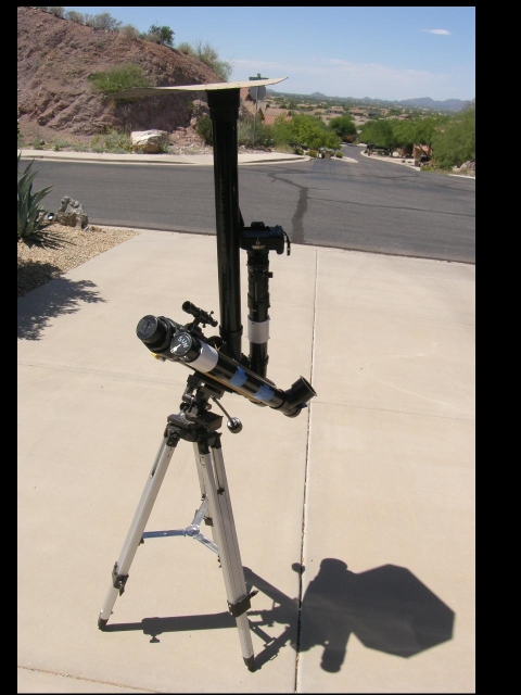
On the above image the tall pipe that is nearly vertical supports a cardboard sunscreen to shield the camera and, partially, the observer too.
The image below shows the construction of the device. The diffraction grating is located inside the plastic tube on the right side and the sighting device is the plastic tube on the left side. Visible on the first photograph, but not visible in this view, is a slit on the far end of the right tube (the spectrograph tube).
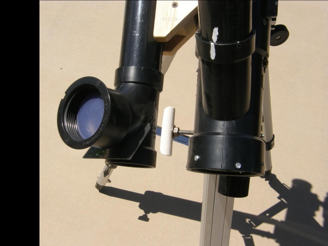
This is a closer view of my homemade solar spectral device. The mirrored diffraction grating in the right tube is attached to a vertical threaded rod. The rod is attached to the white handle that allows the grating to be rotated about the threaded rod. The tube on the left has a plastic mirror mounted at 45 degree angle to project the image of the sun onto a plastic viewing screen for aiming the solar spectrograph at the sun.
The image below shows the capped end of the right tube protecting the diffraction grating and the mechanism that rotates it.
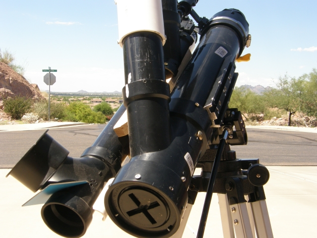
The capped end of the right tube can be removed by simply unscrewing it.
The above view shows that I have opened the back to show the flat mirrored diffraction grating that I purchased from eBay for use in this spectrograph. It was inexpensive because it was without any technical information that would characterize the grating.
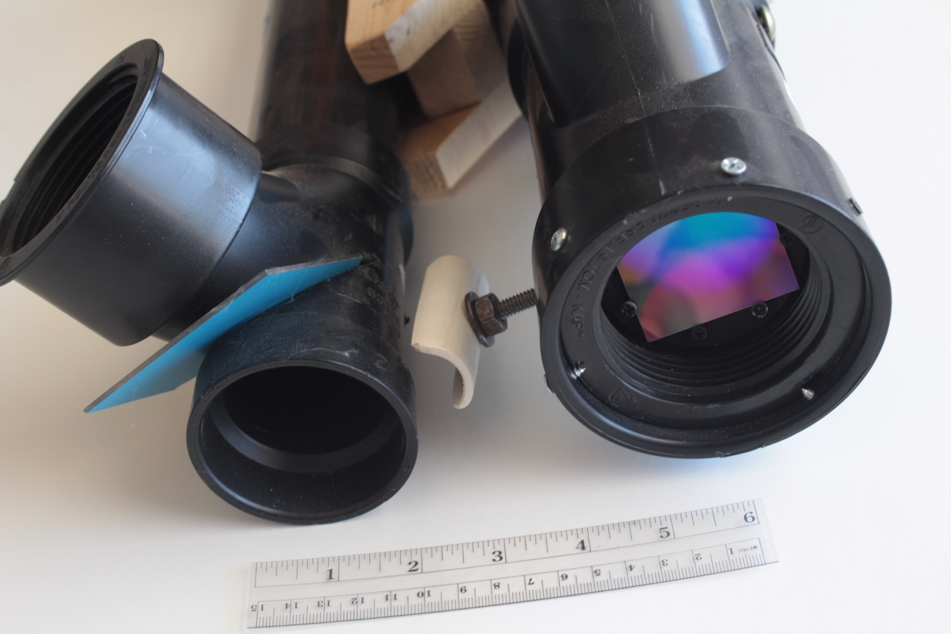
The image below shows the plumbing fixture that contains the diffraction grating on the solar spectrograph and the original box for the diffraction grating.
<
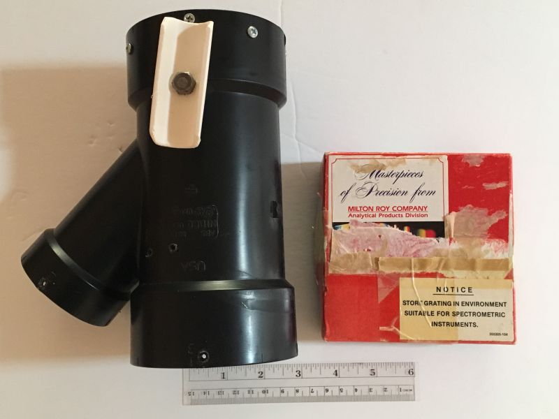
The above image shows the angle between the straight pipe, which has a larger diameter to accommodate the size of the diffraction grating, and the smaller diameter side pipe to be approximately 45 degrees. The rod to which the handle is attached is at the vertex of this angle for the center lines of both pipes, although the slight lean of the larger pipe distorts this view.
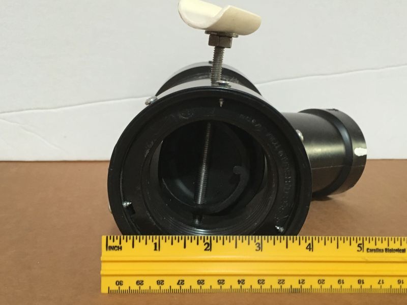
The image below shows the view with the end cap unscrewed. In this view the diffraction grating is rotated forward to face the slit of the device.
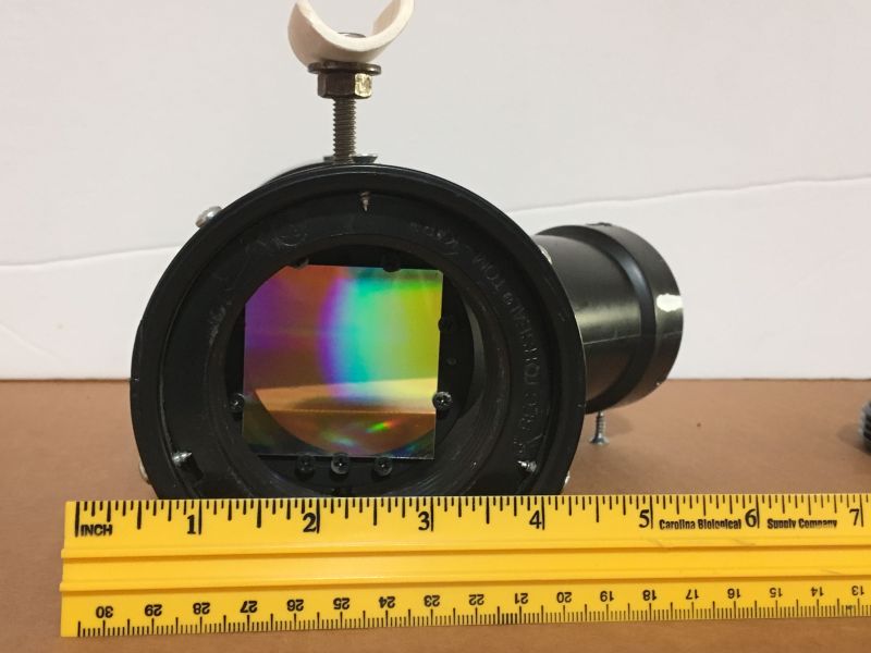
The view above shows the same scene as the previous image, but with the threaded rod rotated 180 degrees. This rotation exposes the bright surface of the commercial diffraction grating.
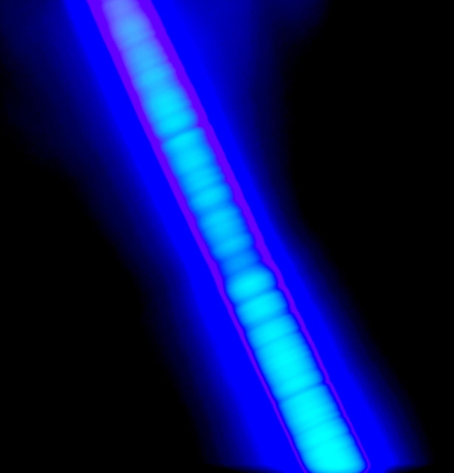
The two images below show a green laser pointer reflected from the mirrored diffraction grating. The grating is oriented perpendicular to the length of the main tube. In these images the laser is laying on a sheet of paper that has a protactor on it.
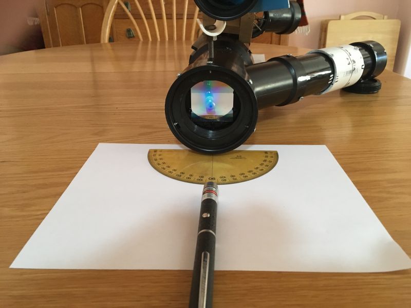
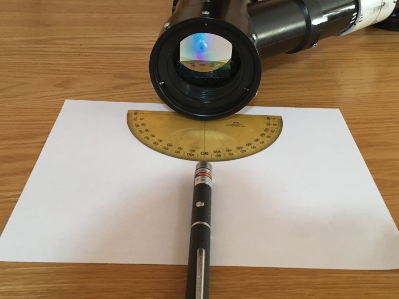
On the image below, the laser is shining slightly downward on the diffraction grating from a slightly elevated position off the bottom edge of the picture. The slight downward angle allows the laser beam to reflect onto the paper. Two very bright spots are produced that can be measured by the protractor to be approxomately 45 degrees apart.
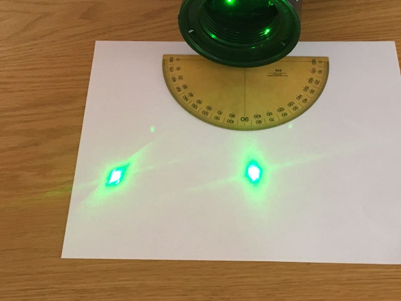
On the above image, the bright spot at the 90 degree position on the protractor is the beam that reflects from the perpendicular surface of the mirrored grating, similar to what would occur if the grating were a regular mirror. What is notable is the very bright beam reflection to the left of this spot. This left beam reflection would be the spectrum, provided the light is not monochromatic (but a laser is monochromatic). It is fortuitous that the angle is identical, or almost identical, to the angle formed by the joining of the two pipes. If the laser had been moved slightly to the left, a similar bright beam reflection would have been produced on the paper to the right, also approximately 45 degrees away from the bright spot at the 90 degree position.
All images that follow use this diffraction grating in this homemade spectrograph to image the spectrum of the sun's light.
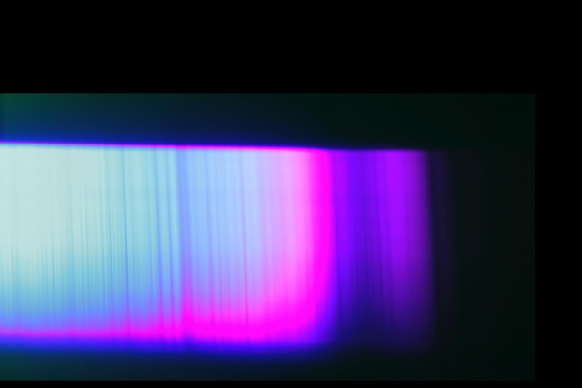
On the image above, a portion of the solar spectrum near the blue end is shown. Notice the thin vertical dark lines. These are the Fraunhofer absorption lines.
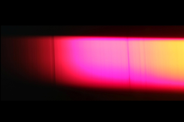
On the image above, the Fraunhofer absorption lines near the red end of the solar spectrum are shown.
The image above shows more Fraunhofer absorption lines in a portion of the solar spectrum that is intermediate between the previous two.
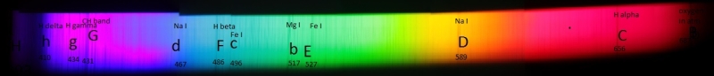
The image above shows the composite view. Several images of the solar spectrum that I made with my spectrograph have been stitched together to produce this view. The capital and lower case letters refer to the original designations by Fraunhofer to the absorption lines. Several of the lines have modern designations with the wavelengths in nanometers given at the bottom.
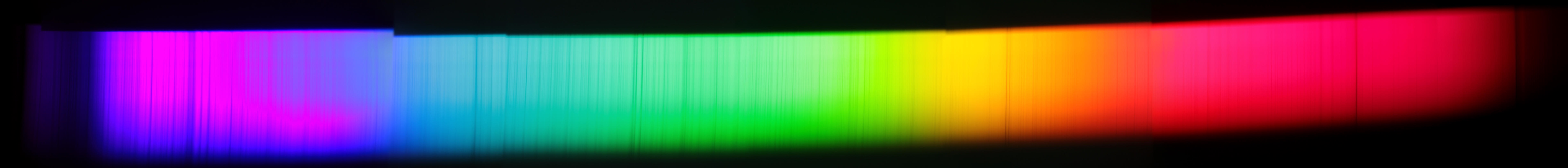
The image above shows the same spectrum as the previous image, but in a larger format and without the labels on the lines.